
The Athearn Maintenance and Upgrade
by John Shaw and Bill Anderson, photos by John Shaw
What follows are simple, yet effective ways to improve the performance of any Athearn diesel locomotive model. The following procedures will require tearing apart your locomotive and modifying different parts, completely voiding any warranty for the product. Proceed at your own risk, but trust me - these modifications won't hurt. They have been performed by many modelers over the years with great success. Follow the directions, keep the drawing that came with your locomotive at hand, and you'll end up with better power in the end.
What's Here
Overview
Disassembly
Upgrading the Trucks
Pearl Drops ?????
Back Together Again
Motor Tuning
Trouble Shooting Tips
Parts
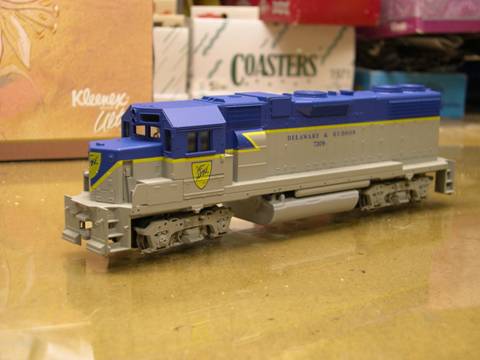
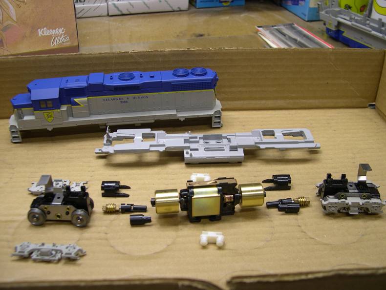
An Overview
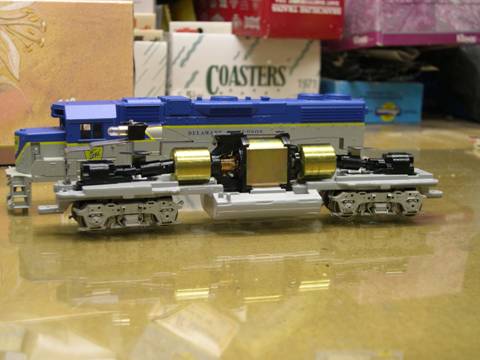
The Athearn drive system . While not the most technologically advanced mechanical system out there, back in the '60s when it was developed, modelers had to deal with the likes of some real ugly drive systems of the time (a lot of them in places like "top of the line" brass models). Most drives back then utilized rubber bands, plastic or rubber tubing, real primitive gearboxes or a combination of several of these, producing results varying from adequate to REAL bad. Couple all that to traction tires, basically a technique to enhance traction for very lightweight models - one wonders why some veteran modelers stuck with the hobby. Athearn, having dealt with rubber band drives, etc., developed a simple chassis design that, probably almost 40 years later, still stands as the most reliable chassis system that exists.
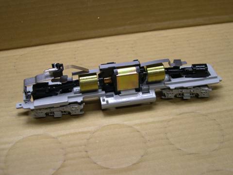
Virtually every diesel model locomotive out there has some variant of this system. Overland, P2K, Atlas, Kato, Bachmann and others, both HO and N scale, all share drive characteristics and similar components with the original Athearn system. Even Athearn's own Genesis SD series locos with the "all new drive system", same deal - a pair of trucks with all wheels driven and picking up power from the rails, a worm gear atop each truck connected to drive shafts with universal joints attached to each end of a motor, all built on a fairly heavy cast metal chassis to keep all wheels on the rail. Every model railroader has or has had at least one and probably still has it because of its reliability. Most of those 40 year old models are still at work on many a layout. Some of mine, albeit with new motors and wheel sets, have withstood ten years of constant use, at times for up to 6-8 hours straight. Heck, back when I was a kid, I found an FP45 buried in a sandbox at a friend's house that he said I could take, "It's busted - go ahead and take it"(Real spoiled, bratty kid with more stuff than he knew what to do with, anyway). What really ticked him off was that, after a GREAT deal of cleaning and polishing by my father and me, it actually ran quite well.
This web site deals with my experiences with Athearn drives; what I've learned while working with them for almost 30 years. I'm positive that experienced modelers won't find a ton of new info here, but if you're a beginner, hopefully you'll find some useful information to keep yours running well.
The Simplicity Of It All
Beginners, this is the perfect time for you to really get acquainted with your Athearn locomotive. Break out the exploded view drawing of your loco and a small flat screwdriver, pull the couplers loose and read on:
All Athearn locos, whether they be switchers, 4 or 6 axle locos, all share the same drive system. Some modifications have been made here and there, and they will be mentioned.
Athearn shells are mounted in one of two ways - a pair of mounting lugs on either side of the chassis thru holes on the side sills (older models) or with four plastic clips molded to the shell, protruding thru four slots in the bottom of the fuel tank. If you have an older one, spread the sides of the shell apart gently with the screwdriver and your fingers until the shell is free. The newer models require a bit more finesse. While pulling up on the shell and gently squeezing the sides, place the screwdriver into the holes and gently (and simultaneously) work the clips until they release, freeing the shell from the chassis.
After the shell is off, compare what you see with the drawing. Now would be a good time to have some paper towels on hand as Athearn is notorious for using large amounts of lubricant everywhere on their drives. You'll want to wipe most of it from the drive (and all of it from your hands).
Pull the metal pickup strip from the top of the motor and put it in the box (the Athearn box will do). Work the clip from the front of the engine using a pair of pliers to remove the light bulb assembly. Many call this the welder in the cab light. Place this also in the box. Neither of these pieces will be re-installed.
Before going any further, take a pencil and mark the chassis with an "X" where the L bracket comes up from the chassis. This will help when it comes time to reassemble the locomotive. (Unless you like playing Gomez Adams and want to have your locomotive run opposite to all your other locomotives) On the top of each truck tower you'll find the worm housing covering the worm gear (where the drive shafts connect). Gently pry them off with a screwdriver - you might want to place a free hand over your work to prevent the housing from flying free.
Once removed, pull the worm gear loose, followed by the drive shafts and universal joints. Don't loose the thrust washers or the bronze bearings on either end of the worm gear shaft. Do this to both trucks. Lift the chassis and the trucks should be free of the chassis. Notice which way the motor sits in the chassis. With a small piece of masking tape and a pencil, mark the front of the motor with an "f" (the direction of the headlight clip). Grasp the motor gently pull up until it comes free from the chassis. The small neoprene motor clips will sometimes come out with the motor, sometimes not. If one or both clips still reside in the chassis, use a dull pencil to poke them out of the chassis. Be careful not to damage these clips. While they’re pretty tough, if they get cut or disfigured, the motor won't mount back in the chassis correctly, causing you to use my name in vain.
Regardless, you should now be holding a bare chassis, and have a whole bunch of locomotive parts in your Athearn box. At this point, if your curiosity has peaked, you can reassemble the unit back to what it was. I suggest cleaning the excess grease/oil from all parts. This will decrease the amount of dirt, dust and crud that the unit will pick up. Just follow the directions in the reverse order. For the full Athearn tune up, read on.
"Gimme filter, oil and lube, please..."
There are plenty of things that can be done to enhance the performance of the stock Athearn drive. What follows are several tricks, some that I've learned from various sources and some that I've come up with on my own. Tools you'll need are:
- #11 Exacto blade & handle
- a set of Jewelers screwdrivers
- Several small needle files
- 220 grit sandpaper
- NMRA track/wheel gauge
- Labelle #106 lubricating grease with Teflon.
- Labelle #102 gear oil
- Some Pearl Drops Tooth Polish will help as well (No, really!!). Here we go:
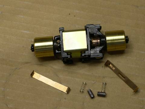
Gently pry the side frames off the trucks - take note on how they came off as well, especially on six axle locos. If the axles are painted as they were on the model shown, it would be safer to remove them after you have split open the gear box and push the pin from the inside. (I tried to pry these off and they broke. I now have to find those spare parts I had laying around here somewhere.)
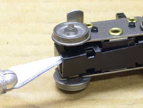
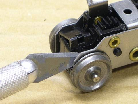
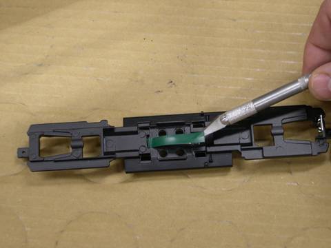
Pull the clips off of the truck assemblies - there should be a small clip on the top and a long clip on the bottom. If you carefully insert your Exacto blade as shown in the photo, you can spread the long clip from the bottom with very little effort. Be prepared to play catch if a clip decides to go flying.
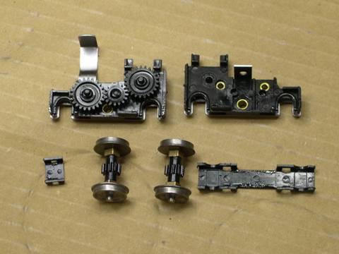
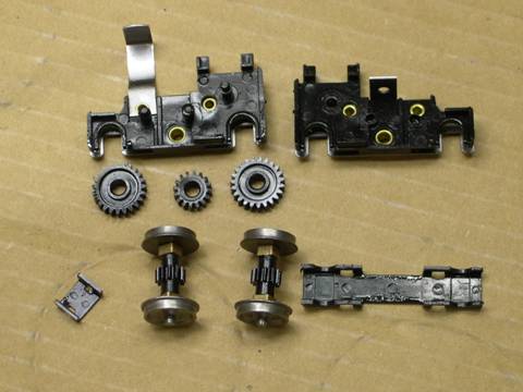
Set the wheel sets aside and pull the case halves apart, notice the orientation of the gears and make note of which ones go where. At this point, I'll put all the parts, wheel sets too, in a small bowl filled with isopropyl alcohol and, using a stiff brush (an old toothbrush is perfect), scrub everything clean. If you have an NMRA track/wheel gauge, pull the wheel sets apart as well. I'll follow up with dish detergent and water. When dry, inspect all the gears for any mold flash, bad teeth, etc. If you find a bad gear, replace it. If you find any flash, CAREFULLY remove it with a small file, sandpaper or a sharp #11 blade.
OK, WHY PEARL DROPS? MY TEETH ARE ALREADY PRETTY WHITE...
And I'm happy for you, really - I am. Pearl Drops possess, besides the minty fresh taste, a fine abrasive that works well to burnish the gear surfaces. (This is also the main reason most dentists do not want you using Pearl Drops on a regular basis.) What you'll be doing is breaking in the running gear in a half hour as opposed to a year. The results will be a smooth running loco with less noise and the motor will have to do less work as well. (Your engine will also smell minty fresh.)
Assemble the gearboxes and, before putting the gearbox halves together, fill them with the tooth polish. Assemble the loco chassis and run the unit forward and backward for about a half hour. I built a couple of jigs for this operation a while back, one for the four axle and one for the six axle locos. They each consist of a four or six axle frame attached to a small block of wood and a motor with leads soldered to each clip for hooking up a power pack. I'll attach the trucks to the appropriate frame, hook up power and run the chassis for 15 minutes in each direction while I work on something else.
After 30 minutes, remove the trucks, tear them down and wash everything with detergent and water. When the parts are dry, assemble the works again. This time, before assembling the case halves together, apply a SMALL amount of grease to the gears. I've been using Labelle #106 Lubricating Grease with Teflon for years with great success. This grease will not migrate and stay put in the gear towers. Whatever you use, make sure that it's compatible with plastics.
BUT, HOW DO I GET THE WHEELSETS BACK TOGETHER WITH THE CORRECT GAUGE?
Athearn wheels are steel and pick up dirt and grease much quicker than Nickel-Silver wheels. At this point, you can change out the axles for Northwest Short Line’s replacement wheels. Twist the wheels and they will come out of each axle. Insert the new wheel sets and use the NMRA gauge to set the distance between the wheels. Look at the axles in the assembly and make sure they line up front to back. The axles will go onto the gears tight, that's what you want. DON'T ream out or enlarge the holes on the gears. Be patient and make sure that all wheel sets are in gauge. Don't forget to place the bronze bearings on the axles. A tiny drop of Labelle #102 gear oil in each bearing is plenty.
After the trucks are back together – side frames and all, place them back on the frame. After making sure that the thrust washers and bearings are in place on the worm gear, place it atop the gear tower. At this point, I put a small dab of Labelle #106 on top of the worm gear, and a drop (Very small drop) of Labelle #102 oil on the brass bearings, then snap the cover in place. Attach the drive shafts and test run the unit. You should notice a much quieter drive.
Going All Out - The Ultimate Athearn Tune Up
So, you've been enjoying your Athearn's for a while, pulled a few trains, done some switching maybe. Maybe you begin to think about just how good these things can run - "How much performance can you squeeze out of them?". Or, maybe you picked up a Kato or an Atlas loco and you'e tried “MU”ing your Athearn to it. It wasn't that much fun, was it. The following tricks will help you do both. Sure, if you have DCC, your speed tables will help compensate for dissimilar locos. But with tuning up, re-motoring, etc., operation will be that much smoother.
The Standard Athearn Motor (and electrical) Tune Up
What follows will help reduce the current draw and overall performance of any open frame Athearn motor. I'll also tell you how to hardwire the chassis, enabling better electrical contact.
There are basically two ways to clean up the motor. The first is described below and entails completely disassembling the motor, removing the flywheels, and using a Dremel to spin the armature while rubbing it with a mildly abrasive sandpaper. The second does not do as good a job, but it may be good enough.
- Assuming that the motor is already off the chassis, pull the flywheels
off each end. Sometimes this is easier said than done. Some flywheels
will just twist right off while others will require a little persuasion.
There are several ways, good and bad, to remove flywheels. While
twisting on both, one will come loose. If the other one fails to
do so, you can do one of two things. Either continue to disassemble
the motor (read below before you do...) until you can grasp the armature,
then twist the other one off OR, with a pair of small serrated pliers,
grasp the shaft between the motor and flywheel, and twist it off.
Try not to chew up the shaft.
If the flywheels come off without a hitch, remove the top and bottom clips. BE WARNED - my modeling areas over the years are home the many small springs, either from Kadee coupler springs or Athearn motor brush springs. Remove the clips slowly, knowing that a spring WILL jump free at its most convenient time. Take the plastic motor ends, metal casing, magnets, thrust washers, clips, brushes and springs and put them in a nice, safe place. If the springs are blue in color or if the brushes are short, they will have to be replaced.
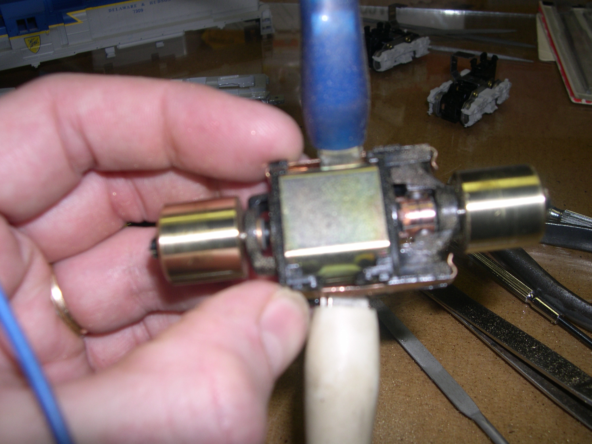
At this point, having a Dremel tool is real handy. I like to chuck the armature/shaft assembly in the tool and, at low speed, polish the commutator (the slotted copper piece at one end of the shaft) with a small piece of 1500 grit paper. I'll follow up with a Pink Pearl eraser until it gleams. This can be done without a motor tool, it just takes more time. After polishing, clean any crud out of the slots with the tip of a #11 blade.
- This is the second procedure and is not quite as thorough as the prior procedure, but you don't have to wrestle with removing the flywheels. All I do is hook up an adjustable DC power supply to the motor, and lay a small file across the armature carefully rubbing the file against the armature until it is clean. You should see few sparks coming from the brushes at this point. I would also recommend that you blow the dust off of the brushes an armature as you file the junk and flatten the armature.
After that, clean up any gunk and/or additional lubrication, assemble
the armature/shaft assembly, magnets, case and ends back together,
putting the clips (without brushes and springs, for the moment) on
to hold everything together. Take a look at the motor brushes. If your
loco is fairly new, the brushes should be in good shape. If yours is
more than ten years old and/or the brushes are starting to look a little
worn, they are probably due for replacement. The local hobby shop,
Athearn.com or Walthers should be able to help.
Now, once you have deemed the brushes worthy, find the brush springs. Cut approximately
1/3 of their length off, leaving - uh - 2/3 of the original spring left over.
What this does is decrease the pressure the spring places against the brush,
creating less friction against the commutator, allowing the motor to run more
efficiently. You're slow speed performance and low-end torque will definitely
improve.
At this point, put the brushes (one at a time is preferred) back in, followed by the springs. Mount the motor back in the chassis, connect the drivelines and take the chassis for a test run. Waddaya think??
THE ELECTRICAL PORTION
Most higher end locos, Kato, Atlas, P2K, etc., are all hard wired for better electrical contact. No friction connections whatsoever, no place for dirt to get trapped in between, no place for oxidization to form. The standard Athearn drive can be modified easily to accomplish the same result.
Assuming the locomotive is still disassembled,
Easy procedure here. Pull the motor clip (the one holding the spring/brush in the motor) from atop the motor. Cut one piece of small stranded wire long enough to span from the one truck to the other + 1/2", then a second piece that will span from the center of the motor to one of the truck towers, plus an additional 1/4" or so. Strip each end back about 1/8". Tin each end with a bit of solder. I found slip on tab connectors at Radio Shack that just happen to fit on the tabs coming off of each track. They are inexpensive and allow the disassembly of the motor in the future without having to unsolder the tabs. This also avoids putting any heat anywhere near the trucks. Before I solder the slip on connectors on to the wires, I bend the eyelet up on top of the slip on connector to make it's profile even smaller. Solder both wires into one of the slip on connectors. Solder the other end of the long wire into the second slip on connector. I usually solder the short wire to one of the metal clips from the motor. It is best to do this with the spring/brush clip off of the motor so as to not put any heat into the motor itself.
I recommend using a good quality flux. My personal favorite is Tix, in fact, their solder works well for this operation too. You might have to experiment with wire length. If in doubt, start with longer wire and cut back if necessary. You want the wire a little long so the trucks will swivel freely but not so long as to cause problems. Replace the clip back to the top of the motor.
Connection to the opposite side of the trucks is made through the chassis and is difficult to isolate for DCC applications. I plan to convert my locomotives to DCC in the future, but do this tune up as a separate item to ensure that the modification is functional before continuing on to install a DCC decoder.
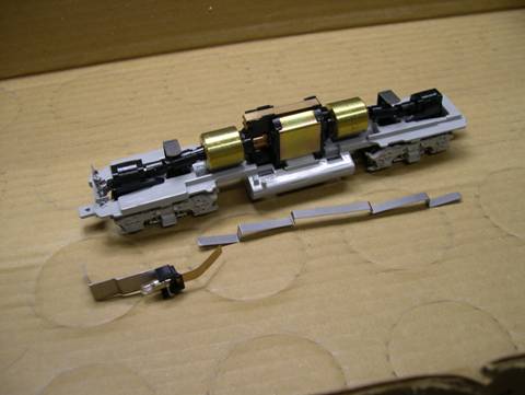
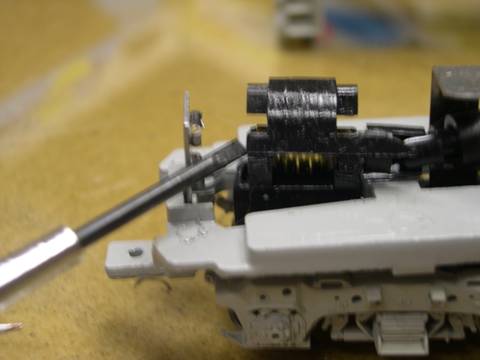
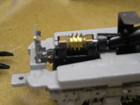
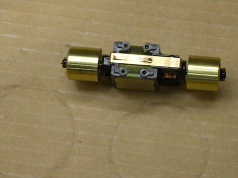
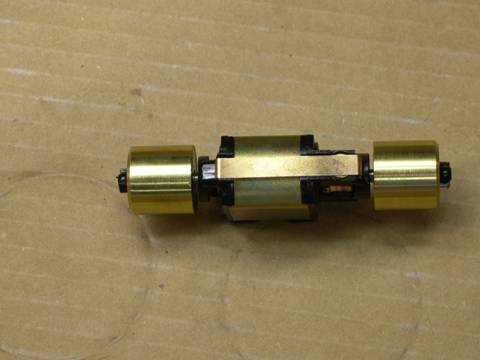
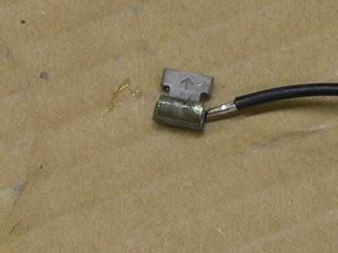
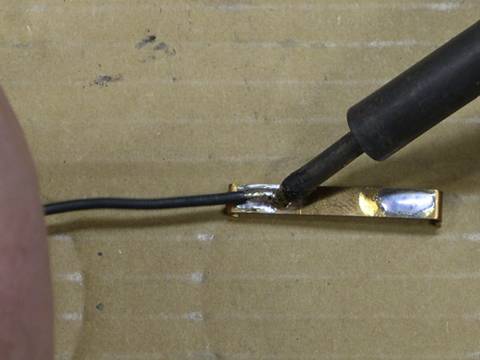
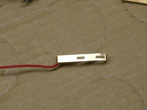
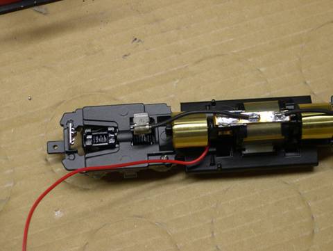
The lower clip needs a bit more work. I clip off the two prongs and then tap the surface with a small hammer to flatten the area where the prongs extended from the clip. I then solder a wire onto the end of the clip as shown in the photo above and then re-attach the clip to the motor.
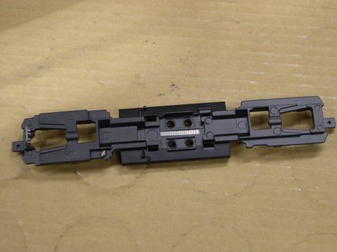
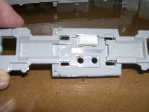
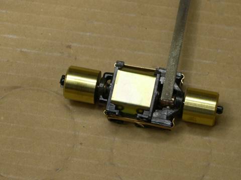
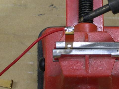
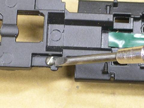
The chassis must be protected from the motor clip. In the photograph above, you can see the bare spot in the between the motor mounts where the motor rests. I use a small piece of electrical tape to cover this area as shown in the second photo above. I then tap a 2-56 screw hole into the chassis as shown in the photo below. I then re-install the motor into the chassis and then attach the wire from the lower clip to the screw in the chassis. I then connect the slip on clips to the truck tabs and and test the chassis. If the wheels are clean the chassis should now run without hesitation.
Now, if you want to get real serious, you can attach leads directly to the metal plates behind each side frame. This procedure definitely takes more time and patience. If there's an interest, I'll list the steps.
WHAT ABOUT THE HEADLIGHT??
Hmmm. Honestly, I'm in the habit of removing it and tossing it as well. It's usually the first thing that I do to an Athearn chassis: "Step #1 - Take large pliers and wrench headlight and bracket from chassis, deposit into trash...".
(Sorry about that... actually I keep the bulb for using in my structures and use the brass strip to make electrical connections for the structures. Everything has a use as long as you have room to keep everything. Now where was that box of string too small to keep…….)
The headlight is easy - cut a third piece of wire long enough to go from the motor to the headlight clip, solder to the motor clip, then to the copper strip atop the bulb housing. Done.
It has often been said that only an arc welder creates more light in a confined space. Besides, the Athearn light bulb casts more light into the cab than out thru the headlight.
Still Want More??
While tuning stock Athearn drives will provide well operating locomotives, to keep them running reliably you need to keep the motor and wheel sets clean, and with stock Athearn drives, you'll be doing this every 2-6 months depending on how often you operate. Admittedly, I'm the laziest person that I know, and I'd rather be detailing or running a choo-choo than cleaning it all the time. To that end, I re-power my locos with Mashima can motors from A-line and nickel silver wheel sets from either Northwest Shortline or Jaybee. As a result, I clean wheels once a year and have never had to worry about the motors. One of my can motors is going on ten years without trouble. AND, they run stride for stride with my P2K, Atlas and Katos.
Troubleshooting Tips
Gunk on wheels: Reduced with extra weight. GP's should weigh in at over 14 oz, SD's even more. SW's and other switchers as much weight as fits in the unit. My heavy F units hardly ever require wheel cleaning, and they are running on highly polished stock sintered iron wheels!
Bad electrical contact between frame and truck bolster, or between frame and bottom motor clip: Even if it looks great, sometimes they are just unexplainably cantankerous. OR bad contact with stock Athearn motor clip assembly due to rust, bent wrong or any number of other problems. These are all fixed by using the "Five-Wire System" to assure positive contact from truck side frames to both sides of motor,
Carbon buildup between motor commutator segments: This should be checked especially if otherwise the motor started running ok, but gradually deteriorated just about when you thought it should be broken in. These particles start to short out the motor & gradually sap its strength. This can be cleared by CAREFULLY cleaning with a very slim instrument such as the smallest jewelers screwdrivers. Make sure that there are no burrs on the edges of the commutator segments.
Weak brush springs: can increase contact resistance between motor frame & commutator. The brushes should be replaced, or the spring slightly expanded to get better contact force. This should particularly be suspected if the motor has overheated due to high current drain, which can anneal the brush spring wire sometimes.
Unit goes bang bang bang bang, or one truck doesn't run smooth or at all: Most likely a split plastic axle gear; if so, one set of wheels will also turn easily & not stay in gauge. The axle gear will need to be replaced & the wheel-set re-gauged.
Any binding anywhere: truck towers, idler gears, u-joints or slip shafts that don't slip. Look for flash on the internal idler gears. Find it & correct as needed.
Or too much slop in the motor shaft., or in the worm shaft: This requires adding shim washers. In the case of the motor, this requires disassembly of the motor to correct. These problems should be suspected particularly if the unit runs noticeably better in one direction and worse in the other.
Check also for the half axles working over to bind against the bearing blocks in the new Athearn trucks, or binding in the sideframe bushing in the old ones: In the old ones, this can often be fixed by adding shims & just a drp of lube oil. Not a drop, just a drp.
Or the insides of the wheels can be rubbing against the internal metal side frames: (new trucks). I sometimes have to bend the internal side frames a whole lot to keep them away from the backsides of the wheels.
This is Jim Fuhrman's "Five-Wire System" for reliable wiring for Athearn and similar locomotive drive trains. It eliminates electrical problems caused by poor contact between the trucks and the frame bolsters, between the motor's bottom clip and the frame, and between the stock strip steel contact strip and the top of the trucks and motor. When this system is installed, the only possible causes of poor electrical contact are the wheels themselves and the motor brush-commutator.
The drawing below shows the system as installed in any B-B locomotive. Similar installations also work for C-C locomotives, but some of the dash-2 styles have the motor reversed in relation to the power trucks. If you install the system in any locomotive and it runs backwards, simply re-install it with the front and rear trucks reversed, and wire #5 on the other side of the motor. The trucks also have to be swapped in this manner when Ernst gears are installed.
Note: when the right rail is positive, the locomotive should run forward.
To make the solder joints easily, tin all wire ends first. Then polish and tin all spots on the trucks where the wires are to be attached. (I use a hot 30-watt soldering iron.) Then touch the tinned spot, tinned wire end and soldering iron altogether to cause the tinning to flow together to complete the joint. The wire should be No. 22 or No. 24 stranded wire and should be dressed with extra length toward the pilot ends of each truck to maintain maximum flexibility. Always use rosin core electrical grade solder!
Wires #1 and #2 replace the stock steel strip. They are soldered directly to the top tab of the power truck, and to the tabs on the top motor clip (which was originally the bottom clip). Wires #3, #4 and #5 replace the frame as an electrical conductor. Wires #3 and #4 are soldered to the side of the truck's metal sideframe, or in some cases to the bolster tab, and arranged in such a way as to not interfere either with the free motion of the truck, or with the wheels. They are joined by tinning about 1/2 inch at the top end of wire #5, twisting the end to form a loop, and crossing the ends of wires #3 and #4 in the loop before soldering all three wires together. If the length of Wire #5 is adjusted properly, no insulation is needed around that joint. The bottom of Wire #5 is soldered to the front end of the bottom motor clip. Note also that when the motor clips have been exchanged, there should be no impediment to the motor seating in a level position in the motor mounts, reducing the possibility of drag on the drive train caused by misalignment of the motor shaft with the worm shafts. Just be careful not to lose any brushes or brush springs when you exchange the motor clips.
Digitrax Decoder Installation for Athearn Locomotives
This installation covers how to install a Digitrax decoder with wires in any Athearn locomotive. If you want a simpler installation that does not require soldering use DH120AT or DH140AT with the Athearn installation harness.
*** Note: This installation is based on installing a Digitrax DH140 decoder in an Athearn Locomotive. The process is similar for any Digitrax mobile decoder with wires.
These instructions assume that you have already run the loco and have established that it is working properly before beginning installation. Remember, installing a decoder in a locomotive will not improve its performance so tune up the locomotive first.
Tools you will need:
- Soldering iron - preferably one that is temperature controlled.
- Solder
- Screwdriver
- Small diagonal cutters for cutting and stripping small wire.
- Tape - electrical or cellophane will do.
- Small amount of insulated wire.
- Drill and tap for screw (suggest 2-56 BRASS).
Now that you have gathered all of your tools, let's begin!
- Carefully remove the shell of the loco.
- Remove and discard the metal strip that runs across the motor from truck to truck.
- Remove the motor from the frame by grasping it and gently rocking it back and forth. The motor is held in place by two small rubber clips that extend into the fuel tank area.
- Turn the motor over and remove the two small copper tabs on the bottom motor strap. There is no need to remove the entire strap at this time.
- Solder the gray wire from the decoder to the bottom motor strap.
- Using the tape from the tools list, insulate the frame from the bottom of the motor. Place a piece of tape on the frame where the motor comes into contact.
- While the motor is removed, select a convenient place to drill and tap the frame for a screw. This will provide better contact for the left side pick up for the motor. Solder the black wire from the decoder directly to this screw.
NOTE: If you intend to keep the forward light mounting bracket as is, the black wire may be soldered here instead of drilling / tapping the frame.
- Put the motor back into the frame.
- Solder the orange wire from the decoder to the top motor strap.
- Connect a jumper wire between the metal tabs sticking up from each truck. Solder the red wire from the decoder to this jumper.
- .Lights - For Half-wave operation - Cut the contact strip at the back of the light fixture approximate 1/4" long and solder the white / yellow decoder lead at that point.
NOTE: If you desire full wave light operation, you will need to devise a different method of mounting the light bulbs, then use the blue decoder wire for light common.
- Track test the loco.
- Install the headlights per the instructions in the Digitrax decoder user's manual.
- Reassemble the locomotive.
- Enjoy!
Parts is Parts
- Light Bulbs
- Screws & Electrical Clips
Even with the advent of super bright white LED’s, small incandescent light bulbs are still easier to work with. LED’s are still quite large and the leads from the LED’s are rigid, while those from a small 1.5V “grain of rice” or “grain of Wheat” light bulb are much easier to work with. In either case, a current limiting resistor is needed to prevent the light from burning out too quickly (or instantly if no resistor is used). One additional comment on “white” LED’s; they are produced by using an Ultra-violet LED with a phosphor coating to produce the white color, much like a florescent light bulb. The problem often encountered is too little or the incorrect phosphor is used in the manufacturer of the LED hence a “Blue” cast white light is produced, not a very desirable affect.
The following table identifies the percentage of current run through either the 15mA or a 20mA bulb respectively assuming 13 Volt operations. This is a simple equation V=IR or Voltage = Current x Resistance, values in Volts, Amps and Ohms. If you operate at a different voltage, you can compute your own values. The resistor values used are standard values available from your local electronics shop. (i.e., Radio Shack). You can get much more precise, but the cost of the resistors goes up. Typical values are +/- 5%.
| 13 Volts | 15ma | 20ma |
| Resistor | ||
| 820 Ohms | 105.69% | 79.27% |
| 910 Ohms | 95.24% | 71.43% |
| 1000 Ohms | 86.67% | 65.00% |
| 1200 Ohms | 72.22% | 54.17% |
| 1300 Ohms | 66.67% | 50.00% |
| 1500 Ohms | 57.78% | 43.33% |
To achieve the longest life from a light bulb, the closer the percentage of current used is to 50% will achieve much longer life. At 50%, the life of either bulb is longer than you’ll be using the locomotive in this life. There is a trade off between life and brightness. You will have to do your own evaluation to determine what brightness you can live with.
Miniatronics: Micro Miniature Bulbshttp://www.miniatronics.com/Merchant2/merchant.mvc?Screen=CTGY&Category_Code=1_1
Micro Miniature incandescent lamps range in size including 0.75mm, 1.2mm, 1.7mm, and 2.4mm diameter. Check the voltage and mA you need for your application.
1.5V
0.75MM Diameter, 20mA Axial [ 10 pcs ]
Code: 18-075-10
Price:$14.95
1.5V
1.2MM Diameter, 15mA [ 10 pcs ]
Code: 18-001-10
Price:$9.75
1.5V
1.2MM Diameter, 15mA [ 20 pcs ]
Code: 18-001-20
Price:$16.95
I actually found the best place to get inexpensive screws for my modeling is at Radio Shack. Packages of 42 2-56 screws of three different lengths are available for a modest price of $1.99 They also carry an assortment of slip on electrical connections that just happen to fit the Athearn L-bracket off of the power trucks. This allows me to have a positive connection to the trucks while allowing me to easily disassemble the locomotive in the future.
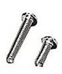
Round-head machine screws. 2-56. 14 each of 1/4", 1/2", 3/4". Pack of 42. $1.99
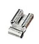
Crimp-On
Quick-Disconnects Right-Angle
5 each: 187 fem NIQD flag (16-14 ga.),
5 each: .250 fem NIQD flag (16-14 ga.). Pack of 10. $1.69
Replacement Wheel Sets
North West Short Line (Makers of
Replacement Wheel Sets)
http://www.nwsl.com/
| Athearn Replacement Wheels | ||
| HO 36” 110 Nickel-Silver Half Axle Wheels (12) | ||
| 37138-4 Outside Frame (Old) | $9.95 | |
| 37143-4 Inside Frame (New) | $9.95 | |
| HO 40” 110 Nickel-Silver Half Axle Wheels (12) | ||
| 37139-4 Outside Frame (Old) | $9.95 | |
| 37141-4 Inside Frame (New) | $9.95 | |
| HO 42” 110 Nickel-Silver Half Axle Wheels (12) | ||
| 37140-4 Outside Frame (Old) | $9.95 | |
| 37142-4 Inside Frame (New) | $9.95 | |
| HO 45” 110 Nickel-Silver Half Axle Wheels (12) | ||
| 37144-4 Inside Frame (New) | $9.95 | |
REFERENCES
The Athearn Maintenance and Upgrade Site by - T. William
and Tammy Anderson
http://hackitup.railfan.net/athearn.html
Tuning up Athearn and other HO scale locomotives - By Jim
Fuhrman
http://trainweb.org/jfuhrtrain/tuneup.htm
Digitrax Decoder Installation for Athearn Locomotives - Digitrax
http://www.digitrax.com/appnote_dash9app.php
Athearn Trains
http://www.athearn.com/
Digitrax Decoder Selection Guide
http://www.digitrax.com/decsel.php
North Coast Engineering
DCC Decoders
http://www.ncedcc.com/